Monday, October 26, 2020

Nanao MC-2000 from Turbo

Just now making an effort to sort out any remaining issues with this Turbo.  While I'm doing minor repairs, I'm also trying to clean the inside of the cabinet, piece-meal, since it's just too big of a job to be done all at once.

Earlier in the week I placed an order for the needed capacitors for the Nanao 20" monitor.  So when the parts arrived on Friday, I pulled the monitor and took it outside for a deep cleaning.  After discharging the tube with a high-voltage probe,  I soaked the tube and chassis down with simple green and used a paint brush to loosen the accumulated dust and grime.  This all gets rinsed down heavily with the garden hose, without a sprayer attachment.  Finally I rinse all of that down with 90% alcohol, followed up with compressed air. 


The monitor was working well enough, with only the occasional wave pattern at the top 1/8 of the screen.  Now that the board was visible again, I notice this burned patch in the front right corner:


When I touched the diode at D505 it was moving around freely.  After removing and testing the two diodes, resistors, and one transistor at Q504, I found D506, R223, and Q504 were all bad.  The emitter leg of Q504 was blown completely away.  Here's a closeup of the drawings for that circuit:


This section controls the Horizontal Position, evidently the damage is not bad enough to make the display unacceptable.  At this point I have to assume perhaps the diode at D506 developed a cold solder joint, which led to the overheating and eventual failure of the stressed components.  That's my theory anyway, so I've placed an order for replacements.  Damn, what an ordeal choosing those turned out to be.

For the time being, I continued replacing the capacitors, which for this chassis was pretty simple.  During this process, testing the ESR, and capacitance, revealed several were bad, most were considerably out of spec.  According to sources, C523 (47uf@50v), located in the high voltage cage, should be replaced with a 100uf@50v, and some suggest replacing the tantalum cap at C408 with a 10uf electrolytic, which I had on-hand.  Evidently this tantalum fails frequently, then you end up with vertical collapse. At my age I can't afford vertical collapse, so the cap was replaced.

Once the new caps were installed, I cleaned an insane amount of old flux from the bottom of the board. 

Any switches and pots on the board ended up being sprayed with Deoxit, as a preventative measure.  I also lightly sprayed the board surface, assuming the mineral oil in the Deoxit can protect the surface from any future problems.

So here it sits, looking very clean now, waiting for those few parts to arrive:


Tuesday, October 20, 2020

Organized Chaos

 More work on Turbo

The engineers at Sega probably knew exactly what they were up against.  However, this game, and the layout of components strikes me as laughably convoluted.


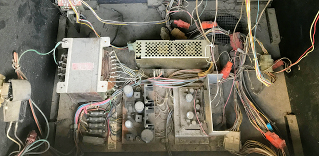
They've got this massive transformer putting out numerous voltages.  Then a switching power supply which only serves +5V, presumably for the logic board.  Next they have a board with three bridge rectifiers, and three 12 volt linear regulators.  There are numerous AC voltages going here and there for light bulbs and sensors, and various other accessories.  They follow all of that up with a very unique little audio amplifier.  

Today, coating all of that, sits 38 years of dust, and who knows what.  If this were a fine wine, I would describe it as smelling like 40 year old ashtray, and the garbage below my high school gym bleachers.

Over the years, I've learned to carefully sort through the bits and pieces in the bottom of these cabinets prior to donning a respirator and hitting the whole mess with the shop vac.  Often the pieces I find are needed later to repair or reassemble some small component.  On some occasions it's been a small spring or clamp that saves the day from total disaster.  Below, a pic of the parts pulled from the filthy recesses of this cabinet:

Notice the two pcb brackets?

As mentioned in an earlier post, this game wasn't doing the best when it came to sound production.  Part of the problem was the 12" woofer.  Even after repairing the speaker, there remained an annoying electrical hum, which overpowered the in-game sounds.

In hopes of cleaning up the sound issues, I decided to replace the old capacitors in the linear power assembly board (834-0120), and the stereo amplifier (834-0121).  

Some people like to replace every single capacitor they find.  Others insist they not be replaced, and that the old capacitors aren't a problem.  I tend to get better results when I carefully work through the power supply, replacing whatever I can.  So to help put this dilemma to rest (at least in my mind), I purchased a capacitor tester.  I chose the Atlas ESR+ by Peak.  In truth, I find that more than half of the old capacitors are indeed good.  In this case, I replaced all capacitors on the two boards, and only found two were bad.  Some had a slightly worse than normal ESR, and others were off when it came to capacitance.

This also gave me the opportunity to clean the gunk away from the boards, as well as the general area around the power supply assembly. 

Here is a shot of the bottom of the linear board, which had to be desoldered, then worked on, then re-soldered back in place.

Yes 15 fidgety little wires 


Here are some before and after shots of the two boards, followed up with a final shot of the power "brick" as it now sits.  Still lots more cleaning and tidying to do.


Yes, still very dirty, but an order of magnitude less dirty.


Monday, October 19, 2020

Sound improvements to Sega Turbo

The Sega Turbo I picked up at last years Free Play was in decent shape, but needed a little TLC, particularly in it's audio department.

"No expense spared," would seem to be the spirit held by the engineers at Sega when designing this classic game.  They added a 12" woofer to provide just that little bit of added bass when passing through tunnels.  This is the second Turbo I've owned, and in both cabinets, the woofer surround had disintegrated.

I wanted to preserve the original speaker, so I started researching speaker repair options.  Thanks to YouTube, that didn't take long.  I quickly located a kit from Simply Speakers.  Part number, for those interested, was the FSK-12F-1 (Single).

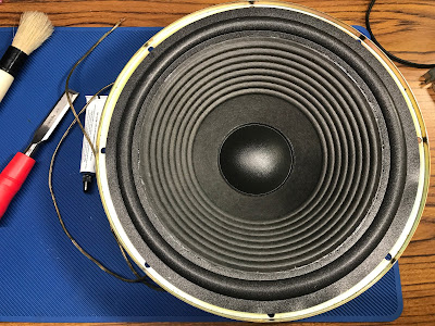
The kit included a brush, glue, the foam surround, and a nice set of instructions.  Here are a few pics of the kit, and the sad state of the 12" woofer:


The process was pretty simple, since the majority of the old foam surround had dissolved entirely.  With a nice sharp box cutter, I removed the thick cardboard material around the outer frame. Carefully setting those pieces aside, I then continued to scrape away the remaining glue and bits of old foam.  As you can see, the paper cone was in excellent condition.


Once I had it down to a nice clean surface, it was a simple matter of gluing the new foam surround to the cone.  After this had dried for several hours, I came back and glued the outer edge of the foam to the frame, then glued the thick pieces of insulating material back to the outer rim.  After allowing this to dry overnight, I cleaned up the dust and any crud with a damp cloth.  


In the end, the newly repaired speaker looks great, and sounds great.  Well it sounds original, great is an overstatement.  Let's just say it sounds like it should.  I highly recommend this process to anyone, the original speaker is totally worth saving for this little bit of effort.